Tesla Model X: Forward Junction Box (Remove and Replace)
Remove
- Position the vehicle on a lift, but do not raise the vehicle at this time.
- Disconnect 12V power (refer to procedure).
- Remove the cowl screen panel (refer to procedure).
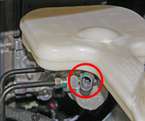
- Disconnect the brake fluid level sensor.
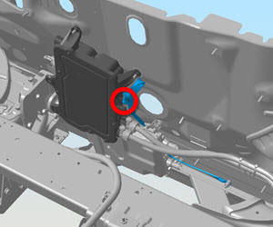
- Release the fir tree clips that secure the 12V harness to the
rear of the fusebox bracket.
.
.jpg)
- Remove the screws (x3) that secure the fusebox bracket to the
body (torque 7 Nm).
.
.jpg)
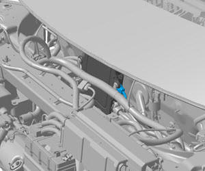
- Release the battery vent tube by gently pulling it away from the
12V battery.
Note: The following image shows the 12V battery ground connection still connected.
.jpg)
- Gently move the fusebox and bracket assembly to the RH side of the vehicle.
- Remove the wiper motor assembly (refer to procedure).
- Release the push clips (x2) that secure the fuse box harness.
.
.jpg)
- Remove the bolts (x2) that secure the wiper mount bracket to the
crossmember (torque 20 Nm).
.
.jpg)
- Remove the nuts (x2) that secure the wiper mount bracket to the
studs on the bulkhead (torque 20 Nm).
.
.jpg)
- If equipped, move the air suspension reservoir out of the
working area:
- Release the clips that secure the LH front air
suspension line.
Caution: Replace any broken clips.
.
.jpg)
- Release the clips (x3) that secure the cowl bracket.
- Release the clip that secures the air lines to the
crossmember.
.
.jpg)
- Release the nuts (x4) that secure the air suspension reservoir (torque 6 Nm).
- Slide the air suspension reservoir to the LH side of
the vehicle, then move it toward the fusebox to allow
access to the front junction box.
.
.jpg)
- Release the clips that secure the LH front air
suspension line.
- Remove the HV battery (refer to procedure).
- Slide battery coolant pump 2 off of the bracket.
- Disconnect the harness from battery coolant pump 2.
- Remove the bolt that secures the battery coolant heater bracket
to the chassis (torque 7 Nm).
.
.jpg)
- Remove the nut that secures the battery coolant heater bracket
to the stud on the bulkhead (torque 7 Nm).
.
.jpg)
- Release the barrel clip that secures the HV cable to the DCDC
mounting stud.
.
.jpg)
- Release the clip that secures the 12V harness to the DCDC mounting stud.
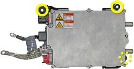
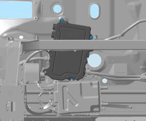
- Remove the nuts (x3) that secure the DCDC converter bracket to
the bullkhead (torque 6 Nm).
Note: Components have been removed in this graphic to aid clarity.
.
- Gently lower the DCDC and battery coolant heater approximately 1
in (25 mm) to access the bottom nut that secures the forward
junction box to the bulkhead. Loosen the nut (torque 6 Nm), then
reinstall the DCDC and battery heater onto the retaining studs.
Note: It is not necessary to remove the nut entirely because the bolt hole is slotted.
.
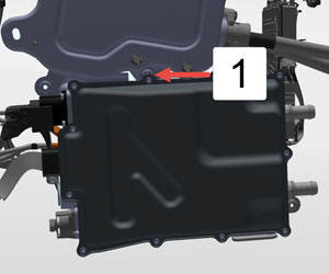
1 Lower forward junction box bolt blocked by DCDC converter - Lower the vehicle.
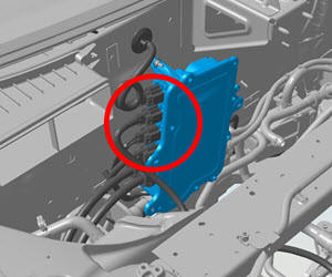
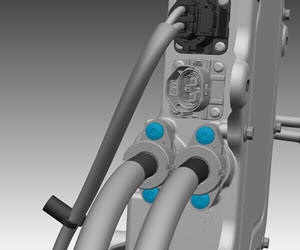
- Disconnect the upper 4 HV cables from the RH side of the forward
junction box.
.
- Release the clips that secure the 12V harnesses to the forward junction box and ECU box.
- Remove the nut that secures the ground strap to the bulkhead
(torque 9 Nm).
.
- Disconnect the 12V harness from the LH side of the forward
junction box.
.
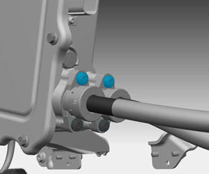
- Remove the screws (x4) that secure the HV cables to the RH side
of the forward junction box (torque 7 Nm). Remove the negative HV
cable, then remove the positive HV cable.
.
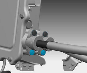
- Remove the upper 2 nuts that secure the forward junction box to
the studs on the bulkhead (torque 6 Nm). Gently pull the forward
junction box toward the front of the vehicle to allow access to the
screws that secure the LH HV cables.
.
- On the LH side of the forward junction box, remove the screw
that secures the top of each HV cable (torque 7 Nm). Do not remove
the lower screws at this time.
.
- Rotate the forward junction box so that the lower LH HV screws can be accessed once the vehicle is raised.
- Raise the vehicle.
- On the LH side of the forward junction box, release the screws
that secure the bottom of each HV cable (torque 7 Nm). Do not
release the cables at this time.
.
- Lower the vehicle.
- Release the HV cables from the forward junction box.
- Remove the forward junction box from the vehicle.
Installation procedure is the reverse of removal, except for the following:
Caution: Replace all Patchbolt(s).