Tesla Model X: 200A Fuses - Wall Connector (Remove and Replace)
Removal
Warning: Only technicians who have been trained in High Voltage Awareness are permitted to perform this procedure. Proper personal protective equipment (PPE) and insulating HV gloves with a minimum rating of class 00 (500V) must be worn any time a high voltage cable is handled. Refer to Tech Note TN-15-92-003, "High Voltage Awareness Care Points" for additional safety information.
Note: This procedure describes how to replace the fuses in the Wall Connector. For information on upgrading the fuses from 100A to 200A, refer to SB-13-50-004, High Power Wall Connector Fuse Upgrade.
- Turn off the electricity to the Wall Connector at the circuit breaker. Verify that the breaker was not already tripped (which would also explain the Wall Connector not functioning). Warning: Electricity must be turned off at the circuit breaker before continuing this procedure. Failure to follow this requirement might result in serious injury or death due to exposure to high voltage.
- Remove the screws (x2) that secure the cover of the Wall
Connector to the casing (torque 1.1 Nm).
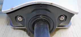
- Release the front cover by pulling it forward far enough to
disconnect the ribbon cable from the cover. Disconnect the ribbon
cable from inside the main enclosure to fully remove the front
cover.
Caution: When removing the front cover, do not damage the ribbon cable. Disconnect the ribbon cable before fully releasing the front cover.
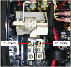
Caution: Do not service the area from the utility input to the left terminal blocks. This wiring is considered house wiring, and must be connected and serviced by a certified electrician.

- Use a properly rated HV voltmeter or multimeter to check for AC
voltage between terminals L1 and L2. Ensure that the correct power
breaker has been turned off to de-energize the Wall Connector.
- Inspect the wiring near the fuses for evidence of heat damage, abrasion, or corrosion. Caution: If the wiring is damaged, the entire Wall Connector must be replaced; close the unit and call a certified electrician to remove the unit.
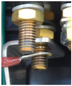
- Remove the screws that connect the bus bars to terminals L1 and
L2.
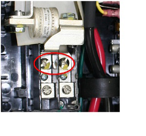
- Use a 13 mm socket wrench to remove the nuts that fasten the bus
bars.
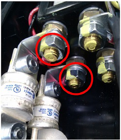
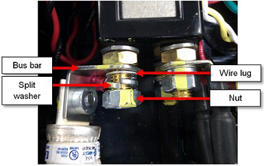
- Before removing the fuse/bus bar assemblies completely, note the
order of the components from bottom to top: nut, split washer, wire
lug, bus bar.
Caution: Take note of the color configuration of the wiring to the contactor before removal. Ensure that all wiring is installed to the same location it was before removal.
- Remove the insulator sheet and fuse/bus bar assemblies.
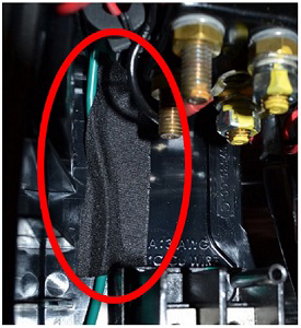
- Ensure that the green ground wire is secured to the back of the
Wall Connector. If it is not, use wire harness tape or other high
temperature resistant tape to secure it to the back of the Wall
Connector.
- Clean the contact surfaces of the new upper and lower bus bars with alcohol wipes.
- Position the new inner fuse. Install the screw at the L2 terminal (torque 3 Nm).
- Install the inner wire's ring lug on the inner contactor stud.
Caution: Position both ring lugs so that the wires point toward the front of the unit at a 45-degree angle, allowing a gap between the inner wire and the outer bus bar. The wires must not touch the bus bars directly.
Caution: Always install the bus bar first and the ring lug second. Installing the ring lug first can result in excessive resistance and overheating.
- Hold the inner wire in position while tightening the nut (torque 5 Nm).
- Use a paint or ink pen to mark the torque position after reassembly, using a different color than manufacturing (manufacturing usually uses yellow). Use one continuous motion to mark the bolt, washer, nut, and bus bar.
- Reinstall the insulator sheet at its original location.
- Repeat steps 2-5 using the L1 terminal for the outer fuse.
- Ensure that the ring lugs are correctly reinstalled to the same location they were before beginning this procedure.
- Use a multimeter to check the resistance between terminals L1
and L2. The resistance should be at least 100 KOhm. If the
resistance is less than 100 KOhm, check for an electrical short due
to improper installation or defective insulation.
- Reinstall the Wall Connector's cover and security screws.
- Turn on the electricity at the circuit breaker.
- Check the front diagnostic lights on the Wall Connector cover. When it is not plugged into the vehicle, the topmost green LED should be steady (not flashing).
- Charge the vehicle with the Wall Connector for 2-3 minutes to verify proper operation of the Wall Connector.