Tesla Model X: Drive Unit - Rear - Small (Remove)
Special tools required for this procedure:
Caution: Use the specified coolant only. In this manual, refer to General Information > Capacities, Fluids, and Lubricants > Fluids.
| Supplier | Part Number | Description |
| Tesla | 1071308-00-B | Small Drive Unit Sling |
| Tesla | 1046674-00-C | COVER, HV, INV, 3.0-150 |
| Tesla | 1057312-00-A | Axle Extractor |
Removal
- Remove the rear subframe (refer to procedure).
- Place a coolant catcher under the subframe fixture.
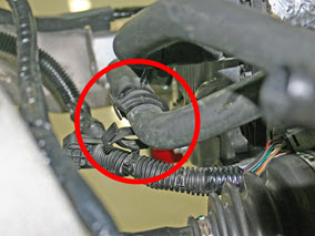
- Release the clip that secures the coolant hoses to the subframe.
- Release the clip that secures the low voltage harness to the
coolant hoses.
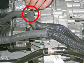
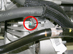
- At the front of the drive unit, release the bolt that secures
the coolant hose bracket (torque 5.5 Nm).
- Plug the holes for the HV cables. Caution: Do not allow coolant to enter the openings for the HV cables.
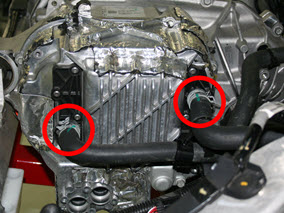
- Release the 2 coolant hoses from the front LH side of the drive
unit.
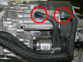
- Release the 2 coolant hoses from the RH side of the drive unit.
- On each side of the subframe, release the 2 grommets that secure
the wheel speed sensor harness.
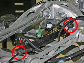
- On each side of the subframe, release the bolt that secures the upper link to the knuckle (torque 140 Nm).
- On each side of the subframe, release the bolt that secures the toe link to the knuckle (torque 130 Nm).
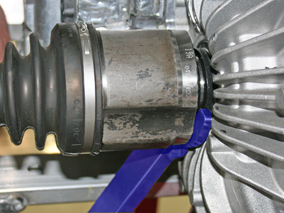
- Use the axle extractor tool to release the halfshafts from the
transmission.
Caution: Do not let the halfshafts rest on the input seal.
Note: When releasing the RH halfshaft, position the tool at the bottom of the halfshaft.
- Remove and discard the cable tie that secures the NVH pad to the
drive unit.
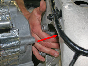
- Remove the NVH pad from the LH side of the drive unit:
- Working from behind the drive unit, release the hook-and-loop straps that secure the NVH pad.
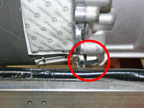
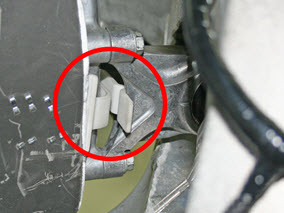
- Working from in front of the drive unit, remove the clip
that secures the NVH pad to the LH side motor mount.
- Pull the NVH pad outboard to remove it.
- Remove the bolt that secures the front of the drive unit to the subframe (torque 90 Nm).
- Remove the bolt that secures the rear of the drive unit to the subframe (torque 90 Nm).
- Release the 3 bolts that secure the LH side motor mount to the drive unit (torque 22 Nm). Note: This causes the LH side of the drive unit to drop slightly.
- Remove the bolt that secures the LH side motor mount to the subframe (torque 90 Nm).
- Push the LH side motor mount outboard.
- Move the transmission jack to the gantry area and secure the
blue, red, and yellow sling mounts:
Note: The black sling mount is not used in this procedure.
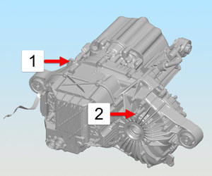
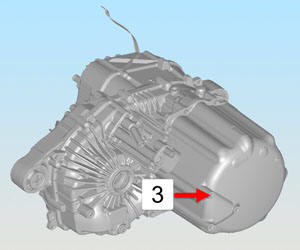
Note: When securing the yellow sling mount, use the hoist ring with the sleeve spacer.1 Red sling mount 2 Blue sling mount 3 Yellow sling mount .jpg)
1 Sleeve spacer - Secure the sling tool to the gantry.
- Lift the drive unit out of the subframe.