Tesla Model X: Subframe Assembly - Front (Remove and Install)
Special tools required for this procedure:
| Supplier | Part Number | Description |
| Tesla | 1021241-00-B | Subframe Fixture, Rear, MDLS |
| Tesla | 1021242-00-C | Subframe Fixture, Front Jig - MDLS |
- If the vehicle is equipped with air suspension:
- Activate "Jack" mode (refer to procedure).
- Depressurize the air suspension system (refer to procedure).
- Remove the HV Battery (refer to procedure).
- Remove the front skid plate (refer to procedure).
- Remove both front wheels (refer to procedure).
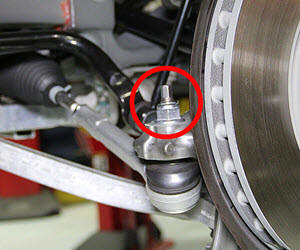
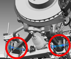
- On each side of the vehicle, release the nut that secures the
tie rod end to the knuckle and disconnect the tie rod (torque 104
Nm).
Caution: To prevent ball joint damage, always hold the ball joint pin with a wrench while loosening or tightening the lock nut.
- On each side of the vehicle, release the nut that secures the
sway bar end link to the sway bar (torque 70 Nm).
Caution: To prevent ball joint damage, always hold the ball joint pin with a wrench while loosening or tightening the lock nut.
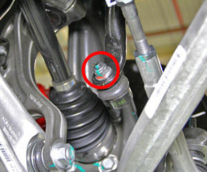
- On each side of the vehicle, release the nuts that secure the
fore and aft lower links to the knuckle (torque 195 Nm).
Caution: To prevent ball joint damage, always hold the ball joint pin with a wrench while loosening or tightening the lock nut.
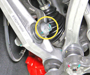
- On each side of the vehicle, release the bolt that secures the
strut to the aft lower link (torque 140 Nm).
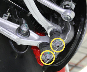
- On each side of the vehicle, mark witness lines on the bolts
that secure the fore and aft lower links to the subframe. Remove the
bolts and remove the lower links from the vehicle (torque 130 Nm).
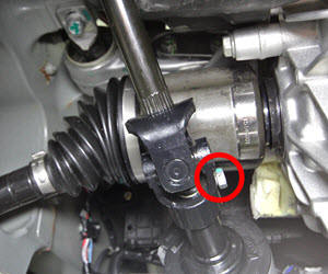
- Mark a witness line on the steering shaft and steering gear
input shaft. Release the bolt that secures the lower steering shaft
to the steering gear (torque 30 Nm). Separate the lower steering
shaft from the steering gear.
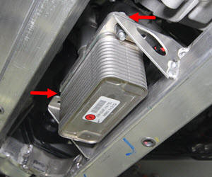
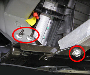
- Release the bolts (x2) that secure the chiller to the subframe
(torque 12 Nm).
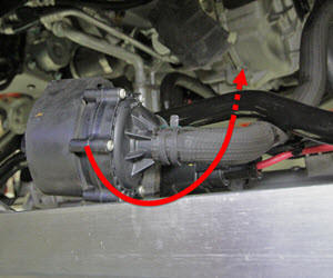
- Disconnect the low voltage harness from battery coolant pump 1.
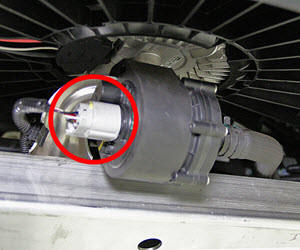
- Remove battery coolant pump 1 from the bracket on the subframe and set the pump aside.
- On each side of the vehicle, remove the bolt (torque 20 Nm) that
secures the condenser fan module bracket to the subframe.
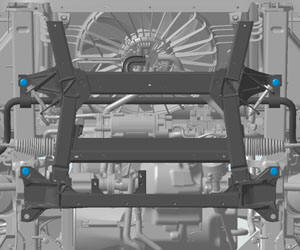
- Install the front subframe jig onto the subframe fixture.
- Install the locating pins into the forward holes on the subframe fixture.
- Have an assistant lower the vehicle. Guide the front subframe onto the fixture.
- Release the bolts (x4) that secure the subframe to the body
(torque 115 Nm).
- Slowly raise the vehicle. As the vehicle is being raised, move
battery coolant pump 1 and its hoses underneath the sway bar to
provide clearance.
- On each side of the vehicle, reinstall the condenser fan module bracket to provide support for the condenser fan module.
Installation procedure is the reverse of removal, except for the following:
Caution: Replace all Patchbolt(s).
Caution: Replace all nylon-insert locknuts.
- Refill and bleed the cooling system (refer to procedure).
- Install all components that were removed for access, except for
the following:
- Front aero shield
- Mid aero shield
- In Toolbox, perform a lock to lock test.
- Transfer the vehicle to a 4-post lift (refer to procedure).
- Torque the front suspension components. Caution: Only fully tighten suspension nuts and bolts when the vehicle is on a 4-post lift and the suspension is in the ride height position.
- Perform a four wheel alignment (refer to procedure).
Subframe Assembly - Front (Remove and Replace)
Removal- Remove the front subframe from the vehicle (refer to procedure).
- Remove and retain the sway bar (refer to procedure).
- Remove and retain the steering rack (refer to procedure).
Installation procedure is the reverse of removal, except for the following:
Use new fasteners to secure the steering rack to the new subframe.
Secure the sway bar to the new subframe.