Tesla Model X: Subframe Assembly - Rear (Installation )
Installation procedure is the reverse of removal, except for the following:
Warning: Only use cleaning agents and solvents in a well-ventilated area.
Caution: Replace all Patchbolt(s).
Caution: Replace all nylon-insert locknuts.
Caution: Ensure that the bolt that secures the spring assembly to the knuckle is inserted towards the rear of the vehicle; the head of the bolt faces the front of the vehicle and the nut is tightened at the rear.
Caution: Only fully tighten suspension nuts and bolts when the vehicle is on a 4-post lift and the suspension is in the ride height position.
Note: Clean the affected areas before installation.
- Large Drive Units built before October 2014 only:
Ensure that no harnesses or cable ties press into the
acoustic padding upon reinstallation. Refer to TN-14-40-002, Noise
Path for Motor Hum, for more information.
- Ensure that the 12V harness does not rest on top of either
of the arches on the subframe.
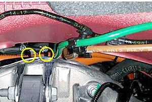
Note: Rotating the clip that secures the
harness to the subframe helps to position the
harness properly.
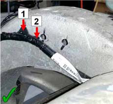
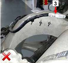
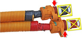
1 Correct: Clip rotated. 2 Correct: Harness routed inboard of subframe. 3 Incorrect: Harness routed on top of subframe. - Replace the cable ties that secure the HV cables when the
subframe is reinstalled. Ensure that the 12V harness is routed
beneath the cable ties.
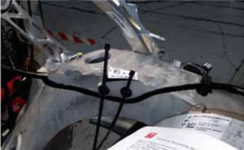
- Ensure that the rearmost section of the 12V harness is
secured to the subframe with cable ties. The harness should
extend out from the rear of the subframe as little as possible.
LH side
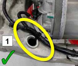
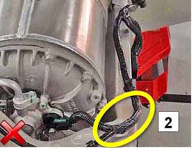
Middle1 Correct: The harness is secure and does not extend past the rear of the subframe. 2 Incorrect: The harness is loose and extends past the rear of the subframe. 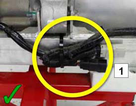
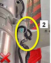
RH side1 Correct: The harness is secured to the rear of the subframe. 2 Incorrect: The harness is not secured to the rear of the subframe. 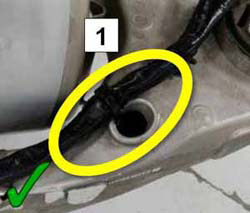
1 Correct:The harness is secure and does not extend past the rear of the subframe. 2 Incorrect:The harness is loose and extends past the rear of the subframe. - After connecting the HV cables to the drive unit, reach
above the drive unit and pull the cables as far forward as
possible.
Note: When securing the HV cables to the subframe, ensure that the ratchets on the cable ties do not press into the acoustic padding
- Ensure that the 12V harness does not rest on top of either
of the arches on the subframe.
Note: Rotating the clip that secures the
harness to the subframe helps to position the
harness properly.
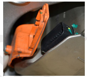
- After connecting the electric parking brake caliper harnesses, install plastic park brake connector covers.
- Small drive units only:
- Inspect the connector seals on the HV cables. If any are damaged, replace them.
- Apply P-80 emulsion to the connector seals.
Caution: Do not apply P-80 emulsion to the HV terminals.
- Resecure the HV cables to the motor.
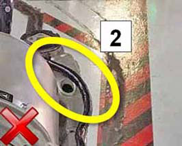
- Large drive units only: To prevent future water
ingress, install new O-rings (1003784-00-A or later) on the drive
inverter cover and apply Silicone Lubricant (1010251-00-A) on both
before installing the cover. Insert the cover at an angle to prevent
damage to the O-rings. Once the left (B+) O-ring is seated, rotate
the cover into position.
- Remove the suspension from "Jack" mode. Set the suspension to Standard and allow the suspension to settle.
- Refill and bleed the cooling system (refer to procedure). Note: Check for coolant leaks while performing the refill and bleed procedure.
- Perform a four wheel alignment (refer to procedure).