Tesla Model X: Electromechanical Brake Booster Assembly (Remove and Replace)
Removal
- Open the driver's door.
- Move the steering wheel fully downwards and away from the instrument panel.
- Move the driver's seat fully rearward.
- Remove the wiper motor (refer to procedure).
- Remove the driver's side lower dash trim (refer to procedure).
- Remove and discard the brake light switch (refer to procedure).
- From inside the vehicle, remove the spring clip from the clevis
pin.
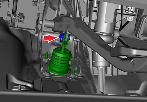
- Depress the brake pedal for clearance and remove the clevis pin.
- Place suitable absorbent material underneath the brake booster assembly and hydraulic lines.
- Using a syringe, remove all fluid from the reservoir. Warning: Do not use a syringe that has been used for oils or other petroleum products. Even trace amounts of petroleum-based fluids can damage seals throughout the brake system, leading to brake failure. Caution: If brake fluid is spilled on a painted surface, wash off immediately with clean water. Note: Place suitable absorbent material around the affected area to absorb any possible fluid spillage.
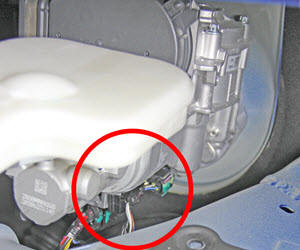
- Disconnect the brake fluid level sensor electrical connector.
- Disconnect the pedal travel sensor and ECU connectors from the
brake booster.
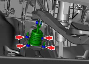
- From inside the vehicle, remove the nuts (x4) that secure the
pedal to the brake booster assembly (torque 23 Nm).
Caution: Replace all nylon-insert locknuts.
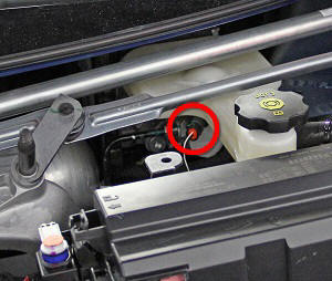
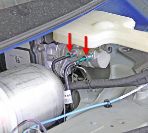
- Release the flare fittings (x2) that secure the front and rear
hydraulic lines to the master cylinder (torque 18 Nm).
Caution: If brake fluid is spilled on a painted surface, wash off immediately with clean water.
- Remove the booster from the underhood area by pulling it forward and rotating it clockwise.
Installation procedure is the reverse of removal, except for the following:
Caution: Ensure that 12V power is disconnected before installing the brake booster assembly and bleeding the brakes.
Caution: Use extreme caution when handling the brake booster assembly assembly. Do not touch the input rod, pedal travel sensor connector, or ECU connector unless otherwise noted.
Note: Clean the affected areas before installation.
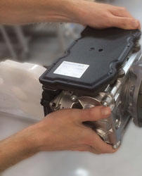
- Handle the booster so that the ECU faces upward; use your
left hand to support the ECU and your right hand to support the
casting.
- Have an assistant hold the brake pedal assembly away from the booster assembly input shaft, then carefully insert the input rod through the hole in the firewall. Caution: Do not allow the input rod to contact the firewall.
- Reconnect all sensors while supporting the booster. Caution: Do not reconnect 12V power yet.
- Bleed the brakes (refer to procedure).
- Replace the brake light switch.
- After the brakes have been fully bled and the brake fluid level sensor connector, pedal travel sensor connector, and ECU connector have been connected, connect 12V power.
- Perform a firmware update.
- In Toolbox 2.0, perform the iBooster Test:
- Select Panels > Brakes > iBooster Setup.
- Click the Start/Play button.
- Sit in the driver's seat and pump the brake pedal several times. Check for a short, firm travel when the brakes are applied.
- Perform a road test using a series of brake stops, including at least one full ABS stop. Ensure that there is proper brake pedal feel and performance. If brake pedal feel is not firm, repeat the bleed procedure with 12V disconnected. Caution: Be mindful of brake temperatures; excessive, high-speed stops can unnecessarily overheat the brake system.