Tesla Model X: Handle and Cable Assembly - 80A Wall Connector (Remove and Replace)
Note: This procedure describes how to remove and replace the 80A Wall Connector handle and cable assembly. For instructions on how to remove and replace the 40A Wall Connector handle and cable assembly, refer to procedure 50024002 (refer to procedure).
Removal
Warning: Only technicians who have been trained in High Voltage Awareness are permitted to perform this procedure. Proper personal protective equipment (PPE) and insulating HV gloves with a minimum rating of class 00 (500V) must be worn any time a high voltage cable is handled. Refer to Tech Note TN-15-92-003, "High Voltage Awareness Care Points" for additional safety information.
- Turn off the electricity to the Wall Connector at the circuit breaker. Warning: Electricity must be turned off at the circuit breaker before continuing this procedure. Failure to follow this requirement might result in serious injury or death due to exposure to high voltage.
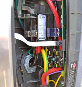
- Remove the screws (x2) and washers (x2) that secure the cover of
the Wall Connector to the casing (torque 1.1 Nm).
- Remove the front cover of the Wall Connector; disconnect the
white flex cable from the interior.
Caution: When removing the front cover, do not damage the ribbon cable. Disconnect the ribbon cable before fully releasing the front cover.
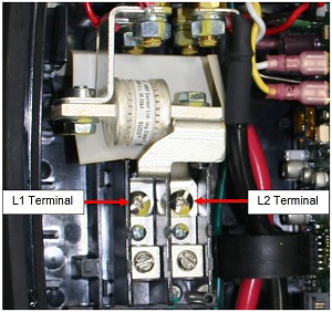
- Use a properly rated voltmeter or multimeter to check for AC
voltage between terminals L1 and L2. Ensure that the correct power
breaker has been turned off to de-energize the Wall Connector.
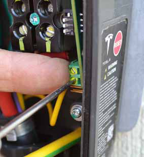
- Loosen the screw that secures the yellow and green grounding
wire (torque 2.3 Nm). Remove the grounding wire.
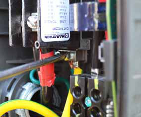
- Loosen the screws (x2) that secure the red and black L1 and L2
wires (torque 17.2 Nm).
Caution: The ferrules on the ends of the L1 and L2 wires are one-time-use only. The ferrules or the handle and cable assembly must be replaced if they have been previously installed.
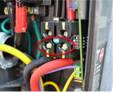
- While holding the green terminal block in place with a finger,
loosen the screws (x2) that secure the purple and yellow wires
(torque 1.1 Nm) to the block. Remove the wires.
Note: Make sure to hold the terminal block in place so it does not bend away from the printed circuit board.
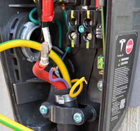
- Remove the red and black L1 and L2 wires.
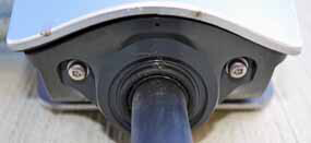
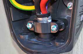
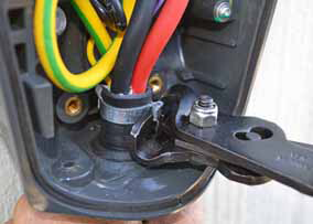
- Remove the screws (x2) that secure the plastic clamp to the
casing (torque 3.4 Nm).
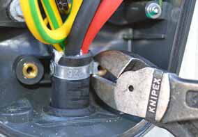
- Use a diagonal cutter to cut the pinch clamp away from the
cable.
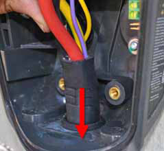
- Pull the cable down through the casing until the wires are free.
- Route the free end of the new cable up through the casing.
- Slide a new pinch clamp onto the cable.
- Use a clamp pincer to install the new pinch clamp.
- Connect the wires and install the plastic clamp in the same order as removal (steps 4 through 8 of the "Removal" section). Caution: The ferrules on the ends of the L1 and L2 wires are one-time-use only. The ferrules or the handle and cable assembly must be replaced if they have been previously installed.
- Reconnect the white flex cable; reinstall the front cover of the Wall Connector.
- Reinstall the screws (x2) that secure the cover of the Wall Connector to the casing (torque 1.1 Nm).
- Turn on the electricity at the circuit breaker.
- Check the front diagnostic lights on the Wall Connector cover. When it is not plugged into the vehicle, the topmost green LED should be steady (not flashing).
- Charge the vehicle with the Wall Connector for 2-3 minutes to verify proper operation of the Wall Connector.