Tesla Model X: Subframe Assembly - Rear (Remove)
Note: Loosen suspension fasteners by hand, then use a cordless electric drill with a 3/8 in drive adapter and a 3/8 in drive air ratchet wrench.
Warning: Only technicians who have been trained in High Voltage Awareness are permitted to perform this procedure. Proper personal protective equipment (PPE) and insulating HV gloves with a minimum rating of class 00 (500V) must be worn any time a high voltage cable is handled. Refer to Tech Note TN-15-92-003, "High Voltage Awareness Care Points" for additional safety information. Warning: If the vehicle has air suspension, activate "Jack" mode on the touchscreen before raising and supporting the vehicle.
Removal
- Prepare the vehicle for lifting:
- Air suspension vehicles only: Put the vehicle into Jack mode.
- Put the vehicle into Tow mode.
- Support the vehicle, but do not lift it at this time.
- Perform the vehicle electrical isolation procedure (refer to procedure).
- Remove the rear wheels (refer to procedure).
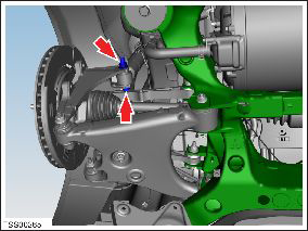
- On both sides of the vehicle, remove the nut that secures the
shock absorber to the knuckle (torque 140 Nm), but do not remove the
bolt yet.
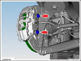
- On both sides of the vehicle, loosen the bolts (x2) that secure
the brake caliper to the knuckle (torque 120 Nm). Remove and support
the calipers.
Caution: To avoid damage to the brake line, the brake caliper must be supported at all times.
- Remove the park brake calipers (refer to procedure).
- Remove the mid aero shield (refer to procedure).
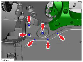
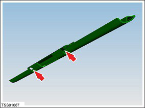
- Remove the subframe shear plates by removing the nut (torque 35
Nm), clips (x2), and screws (x3) (torque 6 Nm) that secure each
shear plate to the subframe.
- If equipped, remove the screws (x2) that secure the rear skid
plate to the subframe (torque 10 Nm).
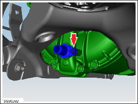
- Large drive unit only: Remove the bolt that
secures the coolant nipple to the coolant manifold (torque 6 Nm).
Note: If the drive unit is being replaced, apply lubricant to the O-ring and transfer the nipple to the new drive unit.
- Release the clips that secure the HV cables:
- Large drive unit: 2 clips to the subframe
- Small drive unit: 2 clips to the body
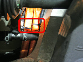
- Large drive unit: 2 clips to the subframe
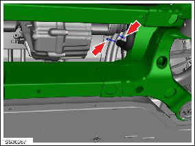
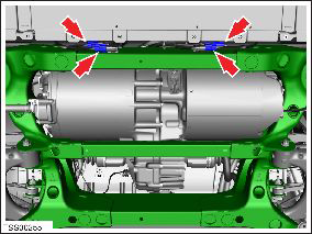
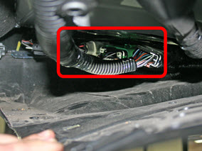
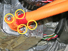
- Disconnect the subframe harnesses from the body harness.
- Vehicles built through September 2014: 4
connectors at the back of the rear subframe
- Vehicles built after September 2014: 3
connectors above the RH side of the rear undershield
- Vehicles built through September 2014: 4
connectors at the back of the rear subframe
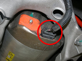
- On the RH side of the drive unit, disconnect the logic
connector.
- Large drive unit:
Small drive unit:
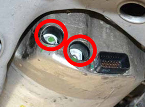
Release the HV inverter cables (x2).
- Large drive unit:
- Release the bolt that secures the drive inverter cover
(torque 3 Nm).
- Remove both O-rings from the drive inverter cover and discard.
- Release the 2 fasteners that secure the HV cables
(torque 9 Nm). Do not remove the cables at this time.
- Release the bolt that secures the drive inverter cover
(torque 3 Nm).
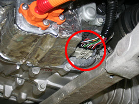
- Small drive unit: Remove and discard the 4
screws that retain the HV cables (torque 7 Nm). Move the cables
away from the drive unit.
- Large drive unit:
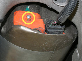
- Small drive unit only: On the top RH side of the drive unit, release the ground strap from the drive unit (torque 6.5 Nm).
- If the drive unit is being removed, drain the gearbox fluid (refer to procedure).
- Drain the coolant from the drive unit.
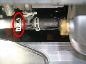
- Large drive unit: Clamp and release the hoses from the transmission and drive inverter.
- Small drive unit: Clamp and release the
hoses from the T-junctions on each side of the drive unit.
Note: During removal of the subframe, 2 coolant
hoses remain attached to the drive unit.
LH side RH side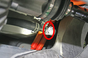
RH side
- Position the subframe fixture beneath the subframe.
- Carefully lower the vehicle so that the subframe table supports the subframe.
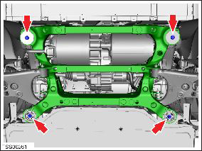
- Remove the bolts (x4) that secure the rear subframe to the body
(torque 140 Nm).
- Carefully raise the vehicle approximately 3 in (75 mm) to gain access to the remaining attachments.
- On both sides of the vehicle, remove the bolt that secures the shock absorber to the knuckle.
- Large drive unit only: Release the remaining
attachments to the drive unit:
- Pull the HV cables out of the drive unit.
- On the top RH side of the drive unit, disconnect the ground strap from the drive unit (torque 6.5 Nm).
- Fully raise the vehicle. Caution: While raising the vehicle, have an assistant monitor the underside of the vehicle. Ensure that no components are still connected and that there is sufficient clearance so that no components are damaged.