Tesla Model X: Front Drive Unit (Remove and Install)
Special tools required for this procedure:
| Supplier | Part Number | Description |
| Bosch | FMG-750 | Transmission Jack 750 Kg Europe only |
| Tesla | 1053350-00-A | Transmission Jack Cradle Adapter Plate Europe only |
| Tesla | 1063141-00-A | 1/2 Ton Economy Transmission Jack North America, APAC only |
| Tesla | 1048391-00-A | Drive Unit Dual Motor Cradle - Delrin white |
| Tesla | 1056566-00-A | Locating Shim Set, Front Motor |
| Tesla | 1056542-01-A | Special 15mm Ratchet Wrench |
- Recover the A/C refrigerant (refer to procedure).
- Remove the HEPA filter housing (refer to procedure).
- Remove the cowl screen panel (refer to procedure).
- Remove the center caps from the front wheels.
- Loosen the axle nuts.
- Remove the HV Battery (refer to procedure).
- Remove the 12V battery cage (refer to procedure).
- Release the 4 bolts that secure the coolant reservoir to the front crossmember (torque 6 Nm). Do not remove the reservoir at this time.
- Carefully lift up the coolant reservoir and disconnect the coolant level sensor harness.
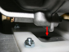
- Clamp the coolant hose at the rear of the coolant reservoir.
.jpg)
- Carefully move the reservoir to the LH side of the vehicle and
plug the coolant hole.
.jpg)
- Disconnect the compressor HV harness from the forward junction
box.
.jpg)
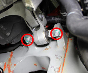
- Remove the screw that secures the ground strap to the compressor
bracket (torque 8 Nm).
.jpg)
- Disconnect the low voltage harness from the compressor.

- Release the nuts that secure the A/C lines to the compressor
(torque 5.5 Nm).
.jpg)
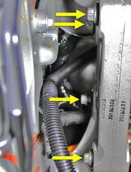
- Have an assistant support the compressor. Release the bolts (x3)
that secure the A/C compressor bracket to the front drive unit
(torque 10 Nm).
.jpg)
- Remove the compressor and bracket from the vehicle as an
assembly.
.jpg)
- Disconnect the ground strap from the drive unit (torque 8 Nm).
- Clamp the drive unit coolant hoses on the front and LH side of
the drive unit. Release the coolant hoses from the drive unit.
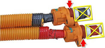
- Disconnect the low voltage harness from the drive unit.
Note: The connector has a 2-part locking system. To release the connector, pull the large red tab towards the rear of the connector, then push down on the smaller red tab.
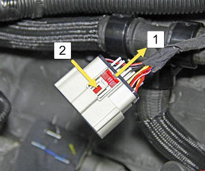
1 Pull the large red tab towards the rear of the connector 2 Push down on the small red tab - Lower the vehicle to access the wheelwell.
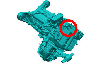
- Working from the LH wheelwell, remove powertrian coolant pump 2
from the bracket.
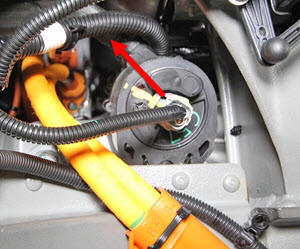
- Clamp the hoses that lead to powertrian coolant pump 2. Release the hoses.
- Move powertrian coolant pump 2 out of the way to gain access the LH side of the drive unit.
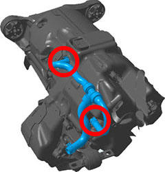
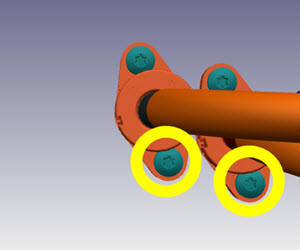
- Remove the lower screws (x2) that secure the HV cables to the LH
side of the drive unit (torque 7 Nm).
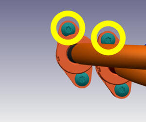
- Release the upper screws (x2) that secure the HV cables to the
LH side of the drive unit (torque 7 Nm). Pull the HV cables away
from the drive unit.
- Remove the front subframe (refer to procedure).
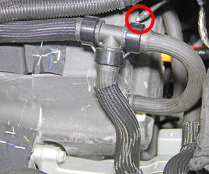
- Remove battery coolant pump 2 from the bracket on the chassis.
Note: Battery coolant pump 2 is near the RH corner of the bulkhead.
- Clamp the coolant hose on battery coolant pump 2 that leads to the chiller. Release the hose from the pump.
- Move the chiller and coolant pump to the RH side of the working area to provide clearance when removing the drive unit.
- Remove the acoustic padding from the front drive unit.
- Drain the gearbox fluid from the front drive unit (refer to procedure).
- xxx
- Drain the gearbox fluid from the drive unit.
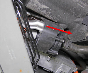
- Remove the RH axle nut.
- Remove the RH halfshaft from the jackshaft.
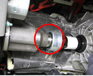
- Remove the RH halfshaft from the hub. Remove the RH halfshaft from the vehicle.
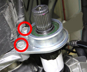
- Remove the bolts (x2) that secure the jackshaft to the drive
unit (torque 30 Nm).
- Remove the LH axle nut.
- Remove the LH halfshaft from the drive unit.
- Remove the LH halfshaft from the hub. Remove the halfshaft from the vehicle.
- Remove the lower RH section of the acoustic cover from the drive unit..
- Install the drive unit cradle onto the transmission jack.
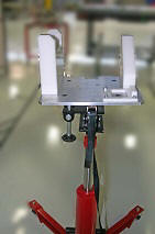
- Position the transmission jack underneath the drive unit.
- Raise the transmission jack to support the weight of the drive
unit. Ensure that the ridge on the base of the drive unit fits into
the channel on the transmission jack.
- Remove the bolts (x2) that secure the LH side motor mount to the
side rail (torque 50 Nm).
Note: The LH side motor mount is removed with the drive unit.
- Release the 4 bolts that secure the RH side motor mount to the
drive unit (torque 75 Nm).
Note: The RH side motor mount remains in the vehicle.
- Lower the drive unit out of the vehicle.
Caution: Ensure that no components are caught on the drive unit as it is being removed.
InstallationInstallation procedure is the reverse of removal, except for the following:
- Refill and bleed the cooling system.
- Recharge the A/C system.
- Apply P-80 emulsion to the connector seals on the HV
cables before securing the HV cables to the drive unit.
Caution: Do not apply P-80 emulsion to the HV terminals.
Caution: Carefully inspect the connector seals. If any are damaged, replace them.